In today’s interconnected digital world, the Open Systems Interconnection (OSI) Model serves as a foundational framework for understanding how data is transmitted across networks. Whether you’re a student, network engineer, or cybersecurity professional, mastering the OSI model is crucial for diagnosing and designing reliable communication systems.
In this guide, we’ll take a deep dive into the 7 layers of the OSI model, their functions, examples, and why the OSI model still matters in 2025 and beyond.
What is the OSI Model?
The OSI (Open Systems Interconnection) Model is a conceptual framework developed by the International Organization for Standardization (ISO). It standardizes the functions of a telecommunication or computing system into seven distinct layers, making it easier to understand, develop, and troubleshoot network systems. Each layer has a specific role and interacts with the layers directly above and below it.
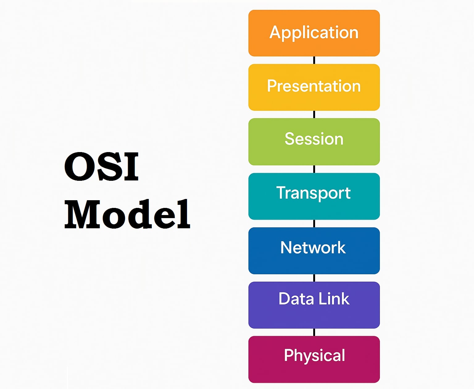
Overview of the 7 Layers of the OSI Model
| Layer Number | Layer Name | Function |
|---|---|---|
| 7 | Application | End-user services and interface |
| 6 | Presentation | Data translation and encryption |
| 5 | Session | Connection management |
| 4 | Transport | Reliable data transfer |
| 3 | Network | Routing and addressing |
| 2 | Data Link | Node-to-node data transfer |
| 1 | Physical | Raw bit transmission |
Layer 1: Physical Layer
The Physical Layer is the first and lowest layer in the OSI (Open Systems Interconnection) Model. It is responsible for the physical connection between devices and the actual transmission of raw binary data (bits: 0s and 1s) over a communication medium such as copper wires, fiber optics, or wireless signals.
Key Functions of the Physical Layer:
- Bit Transmission:
- Transmits raw bits (not data or frames) over the physical medium.
- Converts digital data into electrical, optical, or radio signals depending on the medium.
- Bit Synchronization:
- Ensures that both sender and receiver are synchronized at the bit level using clock signals.
- Bit Rate Control:
- Defines the speed of transmission (i.e., number of bits per second) that both ends can handle.
- Physical Topology:
- Determines how network devices are physically arranged (e.g., bus, star, ring, or mesh topology).
- Transmission Mode:
- Defines the direction of signal flow:\n
- Simplex: One-way (e.g., keyboard to CPU)
- Half-Duplex: Two-way, but one at a time (e.g., walkie-talkies)
- Full-Duplex: Two-way, simultaneously (e.g., telephone)
- Defines the direction of signal flow:\n
What Data Looks Like:
- At the Physical Layer, data is in the form of bits (1s and 0s), not frames or packets.
Devices Operating at Layer 1:
- Cables (Ethernet, Fiber Optic, Coaxial)
- Hubs
- Network Interface Cards (NICs)
- Repeaters
- Modems
- Connectors and Switches (some Layer 1 functionality)
Real-World Example:
If you’re connecting a laptop to a router using an Ethernet cable, the Physical Layer is responsible for:\n
- Ensuring that the electrical signals travel properly through the wire\n
- Managing the connectors and pinouts\n
- Making sure that bits are synchronized at both ends
Why It Matters:
- Even the most complex networks rely on this basic physical layer to function. If the cable is unplugged, the network is down—no matter how perfect the higher layers are configured.
- Network issues like damaged cables, bad connectors, or signal interference can all be traced back to Layer 1.
Layer 2: Data Link Layer (DLL)
The Data Link Layer (DLL) is the second layer of the OSI Model and plays a critical role in enabling error-free data transfer between directly connected nodes (devices). It acts as a bridge between the Physical Layer (Layer 1) and the Network Layer (Layer 3) by packaging raw bits into a structured format called a frame and managing how data is placed onto the physical medium.
Primary Responsibilities of the Data Link Layer:
- Framing
- Breaks the raw stream of bits from the Physical Layer into data frames that are meaningful and structured.
- Each frame includes control information like start/end markers and frame length.
- Physical Addressing
- Adds MAC (Media Access Control) addresses of the sender and receiver in the frame header.
- MAC addresses are unique hardware identifiers (like
00:1A:2B:3C:4D:5E) used for local device identification.
- Error Detection and Correction
- Checks for errors in transmitted frames using methods like CRC (Cyclic Redundancy Check).
- Requests retransmission if errors are detected (optional in some implementations).
- Flow Control
- Manages the pace of data flow so that a fast sender doesn’t overwhelm a slow receiver.
- Prevents buffer overflows and ensures smooth data transmission.
- Access Control
- Determines which device has the right to use the communication channel in networks with shared media (e.g., Ethernet).
- Helps prevent data collisions using protocols like CSMA/CD (Carrier Sense Multiple Access with Collision Detection).
What Data Looks Like:
- At Layer 2, data is structured into frames — each frame includes:\n
- Header (with MAC addresses)\n
- Payload (actual data)\n
- Trailer (with error-checking info like CRC)
Sublayers of the Data Link Layer:
- Logical Link Control (LLC):
- Manages communication and provides multiplexing to allow multiple Layer 3 protocols to share the same physical link.\n
- Media Access Control (MAC):
- Handles how devices access the medium and places frames on the physical network.
Devices Operating at Layer 2:
- Switches
- Bridges
- Network Interface Cards (NICs) (also partially operate at Layer 1)
Real-World Example:
Imagine you’re sending a file from Laptop A to Laptop B over a local network. Here’s what the DLL does:
- It wraps the file data in a frame
- It adds the MAC address of both laptops
- It checks for errors in the frame
- It ensures the data is delivered only to Laptop B, even if other devices are on the network
Why Layer 2 Matters:
- Without the Data Link Layer, we’d have no reliable way to detect and correct transmission errors or even ensure that data reaches the correct device on a local network.
- It forms the basis of technologies like Ethernet, Wi-Fi, and VLANs — all of which are vital in modern networking.
Layer 3: Network Layer
The Network Layer is the third layer in the OSI (Open Systems Interconnection) Model and is responsible for routing, addressing, and delivering data packets between devices that are not directly connected. In simple terms, it determines how data travels across multiple networks to reach the correct destination.
Key Responsibilities of the Network Layer:
1. Logical Addressing (IP Addressing)
- Unlike MAC addresses (used at Layer 2), the Network Layer uses logical addresses like IP addresses (IPv4/IPv6) to uniquely identify devices across networks.
- These addresses are assigned based on network location, not physical hardware.
2. Routing
- Finds the best path for data to travel from source to destination across networks.
- Makes decisions using routing tables and protocols like OSPF, BGP, and RIP.
- This is what enables communication between different LANs, WANs, or the internet.
3. Packet Forwarding
- Transfers packets from one router or hop to the next until it reaches the final destination.
- Each packet has a destination IP address, which routers use to decide where to send it next.
4. Fragmentation and Reassembly
- If a packet is too large for the next network segment, it is fragmented into smaller parts.
- The destination reassembles the fragments into the original message.
What Data Looks Like:
At the Network Layer, data is formatted as packets. Each packet typically includes:
- Header: IP address of sender and receiver, TTL (Time to Live), protocol information
- Payload: Actual data from upper layers
Common Protocols Used in Network Layer:
| Protocol | Function |
|---|---|
| IP (Internet Protocol) | Core protocol for logical addressing and routing |
| ICMP (Internet Control Message Protocol) | Sends error messages (e.g., “Destination Unreachable”) |
| IGMP (Internet Group Management Protocol) | Used for managing multicast groups |
| OSPF/BGP/RIP | Routing protocols that define the best path |
Devices Operating at Layer 3
- Routers
- Layer 3 Switches (Multilayer Switches)
- Firewalls (with routing capabilities)
Real-World Example:
Suppose you’re accessing a website hosted in another country. Here’s what Layer 3 does:
- Assigns a source IP address (your device) and a destination IP address (the web server)
- Breaks data into packets
- Routers examine the destination IP and use routing protocols to decide how to forward each packet through the internet
- If needed, the packets are fragmented and later reassembled
Why the Network Layer Matters:
- Without Layer 3, devices could only communicate within their local networks.
- It enables scalable, global communication—powering everything from small office LANs to the entire internet.
- It is also the entry point for many security controls, like IP-based firewalls, VPN routing, and traffic filtering.
Layer 4: Transport Layer
The Transport Layer is the fourth layer of the OSI (Open Systems Interconnection) Model. It is responsible for the reliable and efficient delivery of data between devices across a network. Unlike the Network Layer, which ensures the data reaches the correct destination, the Transport Layer ensures that it gets there accurately, completely, and in the right order.
Key Responsibilities of the Transport Layer:
1. Segmentation and Reassembly
- Divides large data streams from upper layers into smaller segments for transmission.
- On the receiver’s side, reassembles the segments into the original message.
2. Port Addressing
- Adds port numbers to identify the specific application or service on the device.
For example:- Port 80 → Web (HTTP)
- Port 443 → Secure Web (HTTPS)
- Port 25 → Email (SMTP)
3. Flow Control
- Prevents a fast sender from overwhelming a slow receiver by managing the data rate.
- Uses mechanisms like sliding window protocols to maintain smooth data flow.
4. Error Detection and Correction
- Ensures error-free transmission by detecting errors and requesting retransmission if needed.
- Acknowledges received segments or requests retransmission for lost ones.
5. Connection Management
- Supports two types of communication:\n
- Connection-Oriented (e.g., TCP): Establishes a connection before sending data and ensures delivery.\n
- Connectionless (e.g., UDP): Sends data without establishing a dedicated path.
Protocols Used in the Transport Layer:
| Protocol | Description |
|---|---|
| TCP (Transmission Control Protocol) | Reliable, connection-oriented protocol. Ensures ordered and complete data delivery. |
| UDP (User Datagram Protocol) | Faster, connectionless protocol. Does not guarantee delivery or order. |
| SCTP (Stream Control Transmission Protocol) | Combines features of both TCP and UDP for multimedia and telecommunication services. |
What Data Looks Like:
- At this layer, the data unit is called a Segment (for TCP) or Datagram (for UDP).
- The segment includes:
- Source and destination port numbers
- Sequence numbers
- Checksum (for error-checking)
- Flags (SYN, ACK, FIN for TCP)
Devices and Software Utilizing Layer 4:
- Operating systems (Windows, Linux, macOS)
- Firewalls (Layer 4 firewalls inspect ports)
- Load balancers
- Application servers
Real-World Example:
Let’s say you’re watching a live video stream on YouTube:
- If the stream uses UDP, the video plays smoothly, but may occasionally skip or lose quality without waiting for retransmission.
- If you’re downloading a software file, it uses TCP, which ensures the entire file is delivered correctly and in order, even if it’s slower.
Why the Transport Layer Matters:
- It ensures application-level data is delivered reliably, in the correct order, and without duplication or corruption.
- It’s also critical for security and performance, as many attacks (like DDoS) and optimizations (like load balancing) target Layer 4.
Layer 5: Session Layer
The Session Layer is the fifth layer of the OSI Model. It acts as the communication coordinator between two devices or applications by establishing, managing, and terminating sessions. This layer is responsible for controlling dialogues (sessions) between computers — much like a moderator ensures a smooth, turn-based conversation between two people.
Key Responsibilities of the Session Layer:
1. Session Establishment, Maintenance, and Termination
- Sets up and tears down communication sessions between devices.
- Ensures that both sender and receiver are ready for data exchange.
- Maintains the session until communication ends and closes it cleanly to free up resources.
2. Dialog Control
- Controls the direction and flow of communication.
- Supports both:
- Half-duplex (data flows one way at a time)
- Full-duplex (data flows both ways simultaneously)
3. Synchronization
- Introduces checkpoints or sync points during long data transmissions.
- These checkpoints help resume transmission from the last good point if the session is interrupted, avoiding the need to restart from the beginning.
Real-World Examples of the Session Layer:
- Video conferencing tools like Zoom or Microsoft Teams use this layer to set up, manage, and terminate sessions.
- Online banking applications ensure that your session is active only when authenticated and logged in.
- Remote desktop access tools (like RDP or VNC) depend on this layer to control and synchronize remote sessions.
Common Session Layer Protocols:
| Protocol | Purpose |
|---|---|
| NetBIOS | Allows applications on different computers to communicate on a LAN |
| PPTP (Point-to-Point Tunneling Protocol) | Used in VPNs to create secure sessions |
| RPC (Remote Procedure Call) | Allows a program to request services from another on a different system |
What Happens in the Session Layer:
When a session is initiated:
- A connection is established between the two systems.
- Data flows as per session rules (e.g., duplex settings).
- Checkpoints are inserted if it’s a large or critical file transfer.
- Once the interaction is done, the session is terminated.
Why the Session Layer Matters:
- It provides structure and control to conversations between systems.
- Without it, applications might start sending data before the recipient is ready, leading to errors.
- It’s crucial in scenarios where long-lasting or secure sessions are required (e.g., authentication sessions, streaming, file transfers, etc.).
Example Scenario:
Let’s say you’re using Google Meet to attend a meeting:
- Session Establishment: You log in and connect to the meeting room (authentication + session setup).
- Session Management: Your microphone and camera feed are continuously streamed, while the system ensures both sides stay synchronized.
- Session Termination: You click “Leave meeting” — the session is closed, and resources are released.
Layer 6: Presentation Layer
The Presentation Layer is the sixth layer of the OSI (Open Systems Interconnection) Model. It acts as the translator and formatter for the data exchanged between two systems. This layer ensures that the data sent from the sender’s application layer is in a format the receiver’s application layer can understand, regardless of their system architecture, encoding methods, or operating system.
Key Responsibilities of the Presentation Layer:
1. Translation
- Converts data from the application layer format (like JSON, XML, etc.) into a common format that can be transmitted over the network.
- On the receiving side, it translates the common format back into a form usable by the application.
Example: If one system uses ASCII and the other uses EBCDIC encoding, the Presentation Layer handles the translation.
2. Encryption and Decryption
- Ensures data security by converting readable data into ciphertext (encryption) before transmission.
- Converts it back into plaintext (decryption) after receiving.
Example: SSL/TLS encrypts the communication between your browser and a secure website.
3. Data Compression
- Reduces the size of the data for faster and more efficient transmission.
- Helps conserve bandwidth and minimize transmission time.
Example: Compressing images, audio, or video files before sending via email or streaming.
What Data Looks Like:
- The Presentation Layer deals with data, just like the Session and Application layers.
- It ensures that this data is formatted, secure, and optimized for transfer.
Common Protocols and Formats Used in Presentation Layer:
| Protocol/Format | Function |
|---|---|
| TLS/SSL | Encryption for secure web communication |
| JPEG/GIF/PNG | Image encoding formats |
| MPEG/MP3 | Video and audio compression formats |
| ASCII, EBCDIC | Text character encoding |
| MIME | Email encoding standard |
| XDR, ASN.1 | Data format descriptions for remote communication |
Real-World Example:
Let’s say you’re uploading an image to a cloud storage app:
- The Presentation Layer compresses the image (reducing size),
- Encrypts it (to keep it secure),
- Translates it into a format the receiving system understands.
At the receiving end, it decompresses, decrypts, and converts the image back for viewing.
Why the Presentation Layer Matters:
- It ensures that data is readable and secure, no matter what platform, language, or system you’re using.
- Without it, cross-platform communication would break, encrypted messages would remain unreadable, and files would be bloated or incompatible.
Real-Life Analogy:
Think of the Presentation Layer as a universal language translator:
- If a person speaking French sends a message, the Presentation Layer translates it into English so the receiver can understand.
- It also encrypts the letter (for privacy), and maybe even compresses it to fit into an envelope.
Layer 7: Application Layer
The Application Layer is the seventh and topmost layer of the OSI (Open Systems Interconnection) Model. It is closest to the end user and directly interacts with software applications to enable communication over a network. This layer doesn’t refer to actual applications themselves, but to the services and protocols those applications use to communicate.
Key Responsibilities of the Application Layer:
1. Network Services for Applications
- Provides interface and services to application software like browsers, email clients, file transfer tools, etc.
- Allows software to request network resources such as sending emails, accessing websites, or downloading files.
2. Resource Sharing and Remote File Access
- Enables file transfers, printing, remote login, and directory services.
- Supports client-server communication over the internet or LAN.
3. Email, Messaging, and Web Browsing
- Provides the framework for using email protocols (SMTP, IMAP), web browsing (HTTP/HTTPS), and file transfers (FTP/SFTP).
Real-World Example:
When you:
- Open a web browser and visit
www.example.com→ The Application Layer uses HTTP/HTTPS - Send an email from Gmail → The Application Layer uses SMTP, IMAP, or POP3
- Download a file using Google Drive → The Application Layer uses FTP/SFTP protocols
Common Application Layer Protocols:
| Protocol | Description |
|---|---|
| HTTP/HTTPS | Transfers web pages and data over the internet |
| SMTP/POP3/IMAP | Sends and receives emails |
| FTP/SFTP | Transfers files between systems |
| DNS | Resolves domain names to IP addresses |
| DHCP | Assigns IP addresses automatically |
| Telnet/SSH | Enables remote login to devices |
| SNMP | Manages and monitors network devices |
What Data Looks Like:
- At the Application Layer, data is just raw information ready to be presented to the user (like text, images, emails, etc.).
- No headers or segmentation are added here—this is the point where users “see” the data.
Why the Application Layer Matters:
- It’s the interface between human users and the network.
- It makes possible everyday activities like browsing websites, sending messages, and accessing cloud apps.
- Without this layer, all the communication done by lower layers would be invisible and unusable to the end user.
Real-Life Analogy:
The Application Layer is like a waiter in a restaurant:
- You (the user) give your order to the waiter (application layer).
- The waiter communicates with the kitchen (lower OSI layers) to prepare your food (data).
- Once ready, the waiter delivers your food back to you — neatly served.
Recap of Application Layer:
- User-facing: Interfaces directly with software applications
- Protocol-based: Uses standard protocols like HTTP, FTP, SMTP, DNS
- Service-focused: Provides essential internet services for communication, file access, and more
- Final OSI layer: Data presentation ends here before it reaches you
Why Is the OSI Model Important?
The OSI (Open Systems Interconnection) Model is important because it provides a standardized framework for understanding how different networking protocols and hardware components interact with each other. Even though modern internet communication often uses the TCP/IP model, the OSI model is still highly relevant in network education, design, and troubleshooting.
Here are the key reasons why the OSI model matters:
1. Simplifies Complex Networking Concepts
The OSI model breaks down the complex process of data communication into seven distinct layers. Each layer has a specific function, making it easier to understand, learn, and explain networking concepts—especially for beginners.
2. Helps in Troubleshooting Network Issues
Network administrators use the OSI model as a step-by-step guide to diagnose and isolate problems. For example:
- If users can’t access a website, the issue might be in the Application Layer.
- If data isn’t reaching its destination, the problem could lie in the Network or Transport Layer.
This layered approach allows faster and more efficient troubleshooting.
3. Promotes Interoperability and Standards
The OSI model enables devices from different manufacturers (e.g., Cisco, Juniper, HP) to communicate seamlessly. By following OSI standards, vendors ensure that their hardware and software are compatible with others in the network ecosystem.
4. Supports Modular Engineering
Each layer of the OSI model can be developed and updated independently, which promotes better software and hardware design. This modular approach helps engineers to upgrade or replace individual layers without affecting the whole system.
5. Provides a Universal Language for Networking
Whether you’re working in networking, cybersecurity, or software development, the OSI model gives everyone a common reference point. It creates a shared vocabulary for discussing protocols, functions, and issues.
6. Enhances Security Strategy
By understanding what happens at each layer, security professionals can design multi-layered defenses (defense in depth). For instance:
- Encrypting data at the Presentation Layer
- Filtering packets at the Network Layer
- Using authentication at the Session or Application Layer
7. Aids in Certification and Career Growth
The OSI model is a foundational topic in certifications like CompTIA Network+, Cisco CCNA, CEH, and CISSP. Mastery of the OSI model is often a must-have for anyone pursuing a career in IT, networking, or cybersecurity.
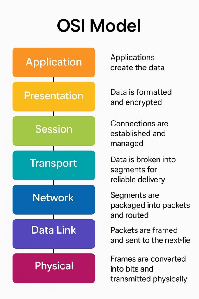
How Data Flows Through the OSI Model
- Sender Side: Data moves from Layer 7 (Application) down to Layer 1 (Physical), with each layer adding its header.
- Transmission: Data is transmitted as electrical/optical signals.
- Receiver Side: Data travels up the stack from Layer 1 to Layer 7, removing headers at each layer.
Example: Sending an Email
- User types the email (Application Layer)
- Email is encrypted (Presentation Layer)
- Session is established (Session Layer)
- Email is segmented (Transport Layer)
- IP Addressing and Routing (Network Layer)
- Framed with MAC address (Data Link Layer)
- Transmitted as bits (Physical Layer)
OSI Model vs TCP/IP Model
| Feature | OSI Model | TCP/IP Model |
| Developed By | ISO | DARPA |
| Number of Layers | 7 | 4 or 5 |
| Flexibility | Modular, Theoretical | Practical, Used in Real-world |
| Layer Separation | Strictly defined | Layers merged (e.g., Application = Layers 5-7) |
| Protocol Independence | Yes | No |
Advantages of the OSI Model
- Clear layer separation simplifies troubleshooting
- Each layer can be updated independently
- Helps in standardization across networks
- Ideal for educational and diagnostic use
Disadvantages of the OSI Model
- More theoretical than practical
- Complex for beginners to grasp
- Modern networks prefer TCP/IP
Protocol Summary Table
| Layer | Protocol Data Unit | Example Protocols |
| 7 | Data | HTTP, FTP, DNS, SMTP |
| 6 | Data | TLS/SSL, JPEG, MPEG |
| 5 | Data | NetBIOS, RPC, PPTP |
| 4 | Segments | TCP, UDP |
| 3 | Packets | IP, ICMP, IGMP |
| 2 | Frames | Ethernet, PPP |
| 1 | Bits | USB, DSL, Ethernet Cables |
Conclusion
Despite being more conceptual than practical, the OSI model remains a fundamental tool for understanding, designing, and troubleshooting network communication. Its layered structure makes complex networking tasks easier to visualize, diagnose, and solve.
Whether you’re preparing for a networking certification, resolving IT issues, or optimizing systems for performance, a deep understanding of the OSI model is invaluable.
Also read: